7 unstable releases (3 breaking)
| 0.4.0 | Jan 4, 2025 |
|---|---|
| 0.3.2 | Oct 8, 2024 |
| 0.3.1 | Sep 30, 2024 |
| 0.2.0 | Sep 16, 2024 |
| 0.1.1 | Sep 11, 2024 |
#177 in Embedded development
59 downloads per month
1.5MB
266 lines
![]()
![]()
embedded-dht-rs
embedded-dht-rs is a Rust library designed to simplify interfacing with DHT sensors in embedded systems.
This library is #![no_std] and depends only on embedded_hal, making it versatile and compatible with virtually any microcontroller.
Support for DHT11, DHT20, and DHT22 Sensors: All three sensors are fully implemented and ready for use.
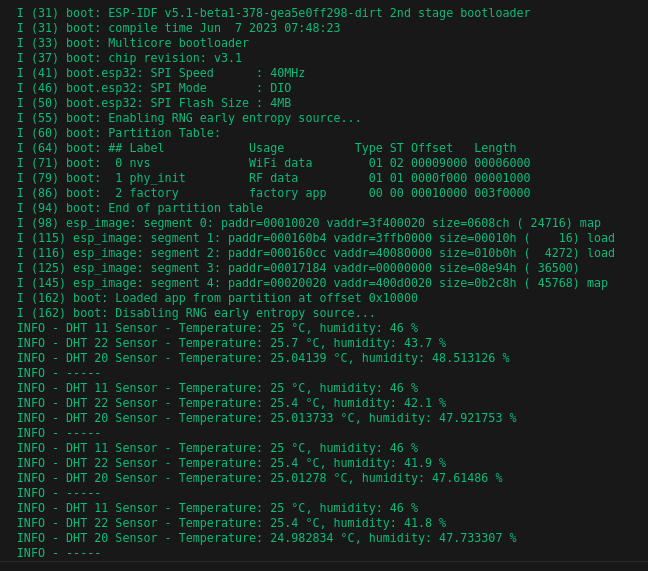
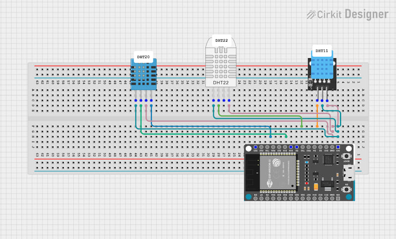
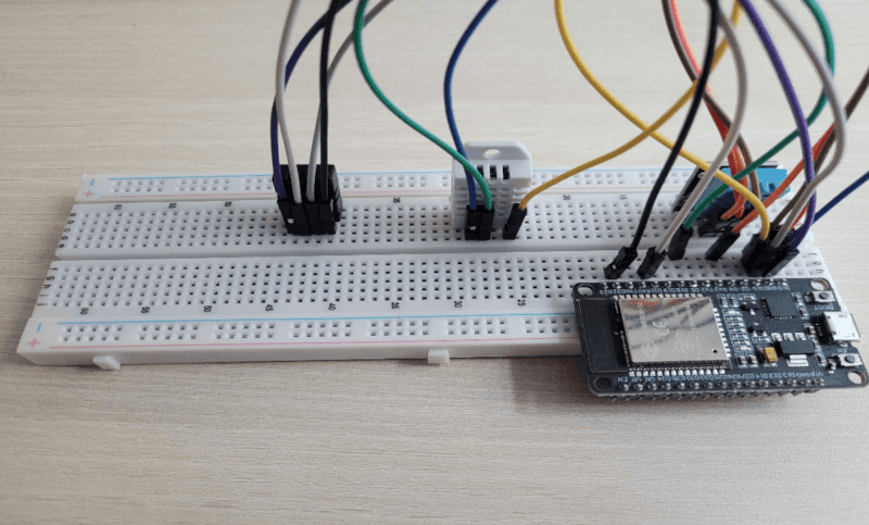
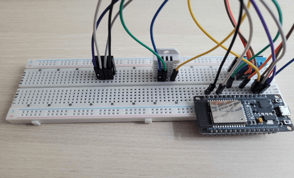
The library has been tested with the ESP32-WROOM, and a detailed example is provided below to help you get started.
Getting Started
Tutorials
Here are some general tutorials that provide brief introductions to embedded programming:
- Part 1 (Introduction) - Introduction to Embedded Systems with Rust: A Beginner's Guide Using ESP32
- Part 2 (LED + Button) - Building a Simple LED and Button Interface with Rust on ESP32
- Part 3 (DHT11 Library) - Building a Rust library for DHT11 sensor
Install
To include the dht11 feature:
cargo add embedded-dht-rs --features "dht11"
To include all features (dht11, dht20, and dht22):
cargo add embedded-dht-rs --features "dht11,dht20,dht22"
Example - ESP32
You can find the full example in the examples folder.
#![no_std]
#![no_main]

use embedded_dht_rs::{dht11::Dht11, dht20::Dht20, dht22::Dht22};
use esp_backtrace as _;
use esp_hal::{
    clock::ClockControl, delay::Delay, gpio::{Io, Level, OutputOpenDrain, Pull}, i2c::I2C, peripherals::Peripherals, prelude::*, system::SystemControl
};
use fugit::HertzU32;

#[entry]
fn main() -> ! {
    let peripherals = Peripherals::take();
    let system = SystemControl::new(peripherals.SYSTEM);
    let clocks = ClockControl::boot_defaults(system.clock_control).freeze();
    let io = Io::new(peripherals.GPIO, peripherals.IO_MUX);

    esp_println::logger::init_logger_from_env();

    let delay = Delay::new(&clocks);

    let od_for_dht11 = OutputOpenDrain::new(io.pins.gpio4, Level::High, Pull::None);
    let od_for_dht22 = OutputOpenDrain::new(io.pins.gpio5, Level::High, Pull::None);
    let i2c_for_dht20 = I2C::new(
        peripherals.I2C0,
        io.pins.gpio21,
        io.pins.gpio22,
        HertzU32::kHz(400),
        &clocks
    );

    let mut dht11 = Dht11::new(od_for_dht11, delay);
    let mut dht22 = Dht22::new(od_for_dht22, delay);
    let mut dht20 = Dht20::new(i2c_for_dht20, delay);

    loop {
        delay.delay(5000.millis());

        match dht11.read() {
            Ok(sensor_reading) => log::info!(
                "DHT 11 Sensor - Temperature: {} °C, humidity: {} %",
                sensor_reading.temperature,
                sensor_reading.humidity
            ),
            Err(error) => log::error!("An error occurred while trying to read sensor: {:?}", error),
        }

        match dht22.read() {
            Ok(sensor_reading) => log::info!(
                "DHT 22 Sensor - Temperature: {} °C, humidity: {} %",
                sensor_reading.temperature,
                sensor_reading.humidity
            ),
            Err(error) => log::error!("An error occurred while trying to read sensor: {:?}", error),
        }

        match dht20.read() {
            Ok(sensor_reading) => log::info!(
                "DHT 20 Sensor - Temperature: {} °C, humidity: {} %",
                sensor_reading.temperature,
                sensor_reading.humidity
            ),
            Err(error) => log::error!("An error occurred while trying to read sensor: {:?}", error),
        }

        log::info!("-----");
    }
}
Implementation Specification
We have gathered all the information you need to understand in order to implement a library like this. Additionally, we’ve included a few comments in the code for those curious about the details, based on the following specification.
The DHT20 differs from the DHT11 and DHT22 because it uses the I2C communication protocol, while both the DHT11 and DHT22 rely on a single-wire signal for data transmission.
Comparison of DHT11, DHT20, and DHT22 40-Bit Data Formats
| Feature | DHT11 | DHT20 | DHT22 |
|---|---|---|---|
| Data Structure | - Byte 1: Humidity Int - Byte 2: Humidity Dec (0) - Byte 3: Temp Int - Byte 4: Temp Dec (0) - Byte 5: Checksum |
- Byte 1: Humidity High - Byte 2: Humidity Low - Byte 3: Temp High - Byte 4: Temp Low - Byte 5: CRC |
- Byte 1: Humidity High - Byte 2: Humidity Low - Byte 3: Temp High - Byte 4: Temp Low - Byte 5: Checksum |
| Precision | Integer only | Higher precision with decimals | Higher precision with decimals |
| Example Temp | 25°C | 25.6°C | 25.6°C |
| Example Humidity | 60% | 60.5% | 60.5% |
| Example Data Bytes | 60, 0, 25, 0, 85 |
2, 93, 1, 0, CRC |
2, 93, 1, 0, 96 |
| Range | Temp: 0–50°C Hum: 20–90% |
Temp: -40–80°C Hum: 10–90% |
Temp: -40–80°C Hum: 0–100% |
Example Schematic
 Click to zoom Click to zoom |
 Click to zoom Click to zoom |
|---|